Overview
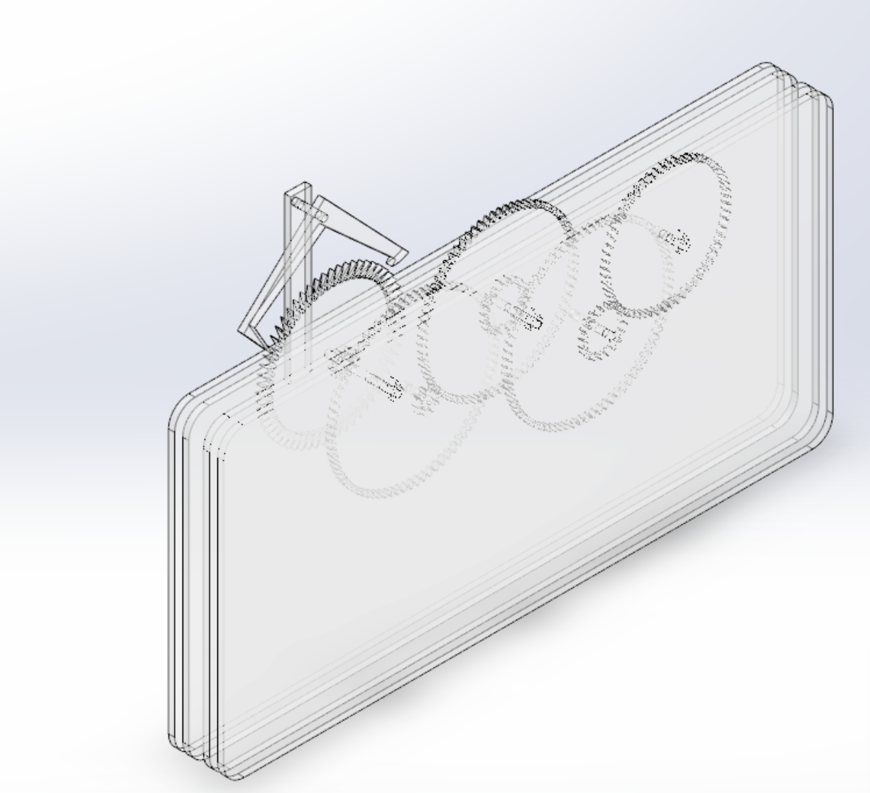
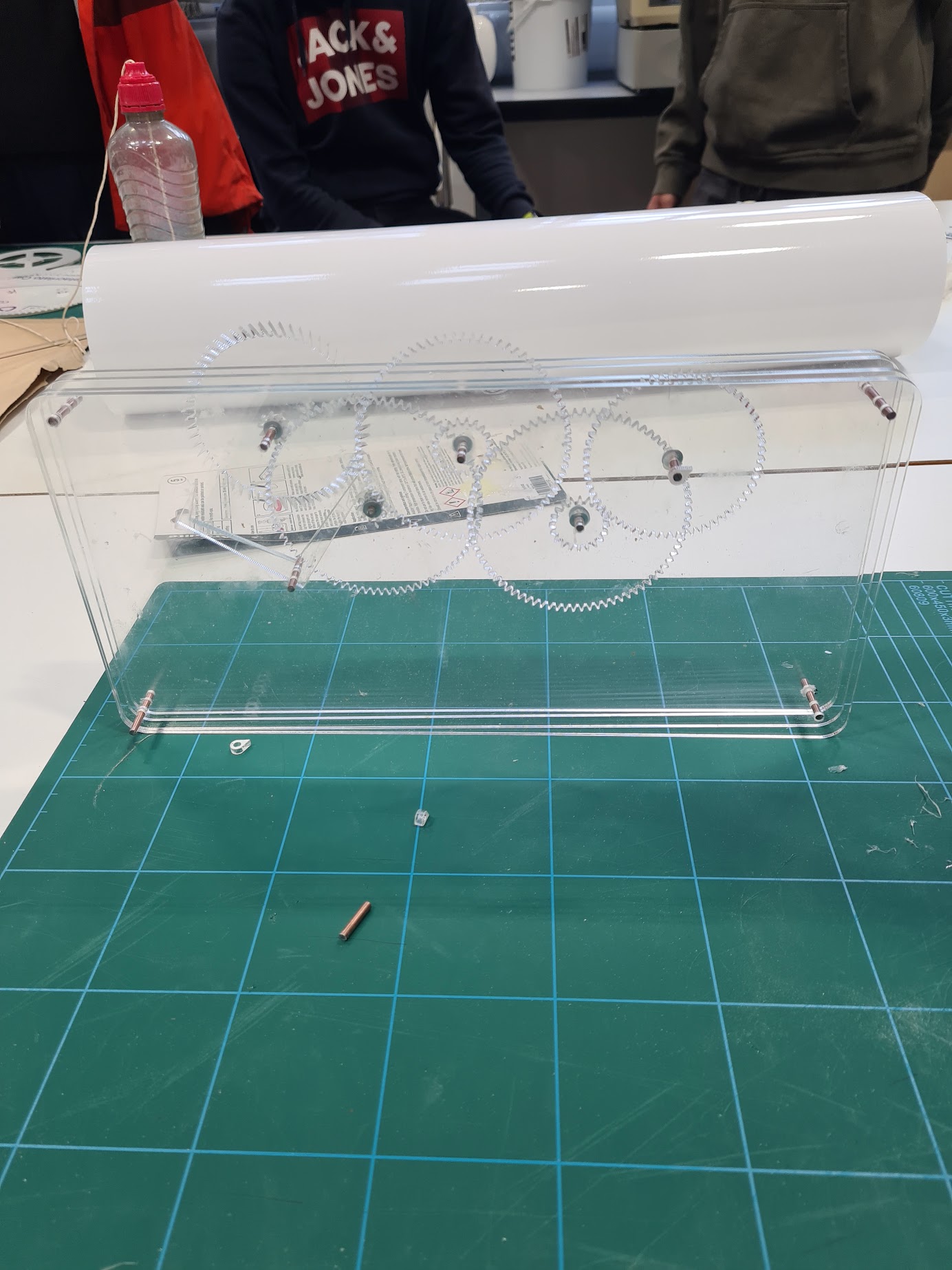
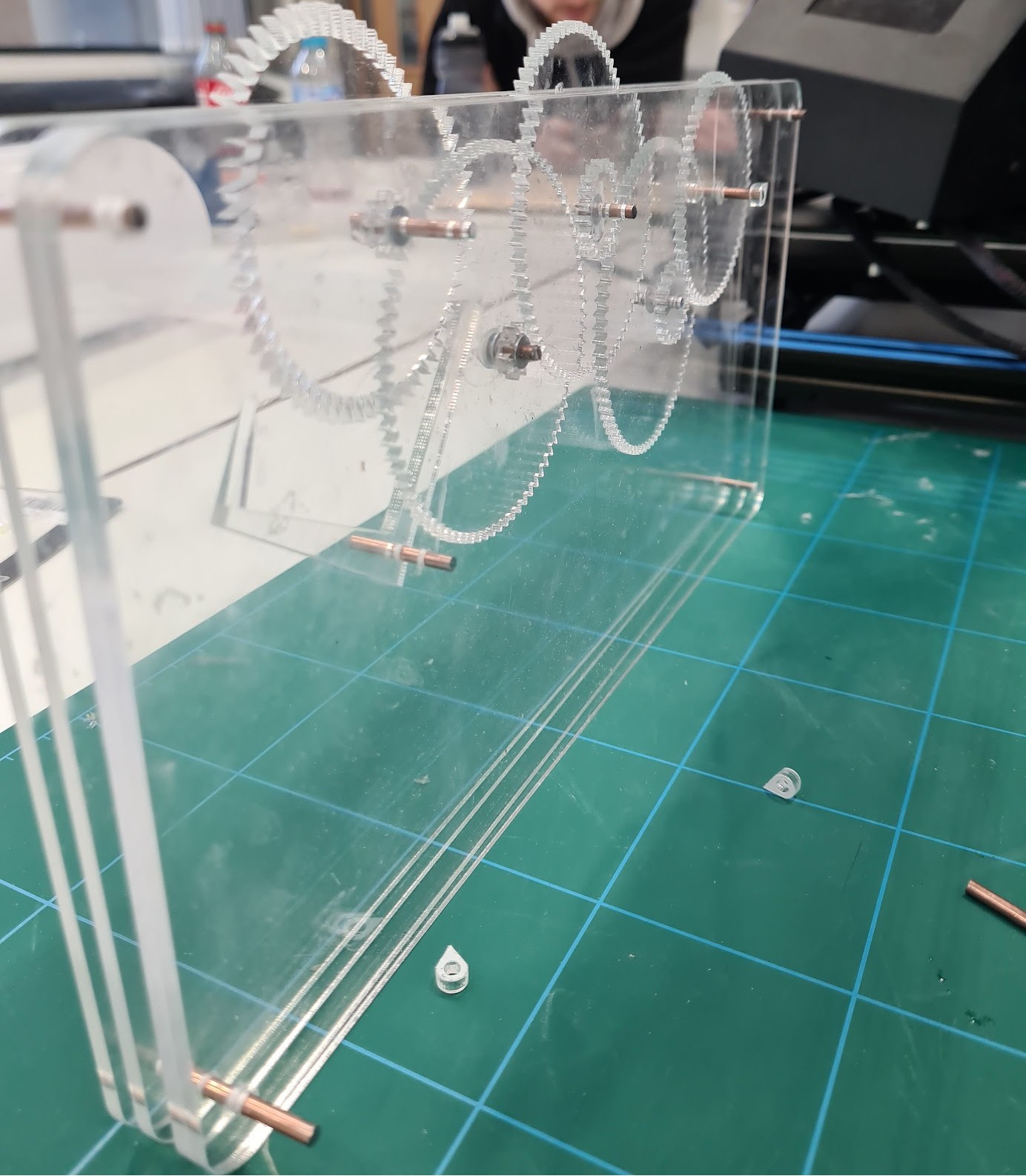
This group project was to design and build a working analog clock by calculating the gear train for the second, minute, and hour hands and producing a clean, manufacturable design. I led the gear-ratio design and 3D modelling. Using SolidWorks (Toolbox gears), I built a continuous train that delivers the standard 60:1 reduction from seconds to minutes and 12:1 from minutes to hours, then laid out a minimalist, inline display with the hands arranged left to right (seconds → minutes → hours) behind a clear acrylic face. I exported the parts to AutoCAD to create 2D profiles for laser cutting, then cut the acrylic panes on a CNC laser. Shafts were made from welding rod, and I assembled the clock using cyanoacrylate and two-part epoxy. The build functioned as intended; the pendulum timing was close but not perfect—off by a few seconds—highlighting fine-tuning opportunities in the regulator and friction management.
Process
- Role: Gear-train design and 3D modelling; integration and assembly support.
- Gear ratios: Calculated a train delivering 1 rev per 60 s (second hand), 1 rev per 3600 s (minute), and 1 rev per 12 h (hour) using SolidWorks Toolbox gears; selected tooth counts to meet center distances and avoid common factors.
- Architecture: Minimalist inline layout; hands arranged left→right, packaged in a clear acrylic “sandwich” frame.
- CAD → CAM: Modelled all components in SolidWorks; exported DXF profiles via AutoCAD for laser cutting.
- Manufacture: Laser-cut acrylic panes and internals on a CNC cutter; cut shafts from welding rod; light hand-finishing for fit.
- Assembly: Dry-fit checks, then bonded with super glue and 2-part epoxy; set gear meshes and axial spacers to minimise drag.
- Commissioning: Hung/leveled the frame, started the pendulum, and verified second→minute→hour tracking.
Outcomes
- Working prototype: All three hands advanced correctly with the intended reductions; overall design matched the minimalist concept.
- Accuracy: Pendulum ran slightly fast/slow (within a few seconds), indicating the need for finer mass/length adjustment and reduced friction at pivots.
- Build quality: Clean laser-cut edges, consistent fit on welding-rod shafts, and rigid acrylic frame after bonding.
- Team delivery: Met the brief, with my ownership of the gear train and CAD enabling fast iteration and smooth handoff to fabrication.
- Lessons learned: Add an adjustable bob for the pendulum, consider bushings/spacers on shafts, and include tolerance allowances in DXFs to improve mesh and long-term stability.
Gallery