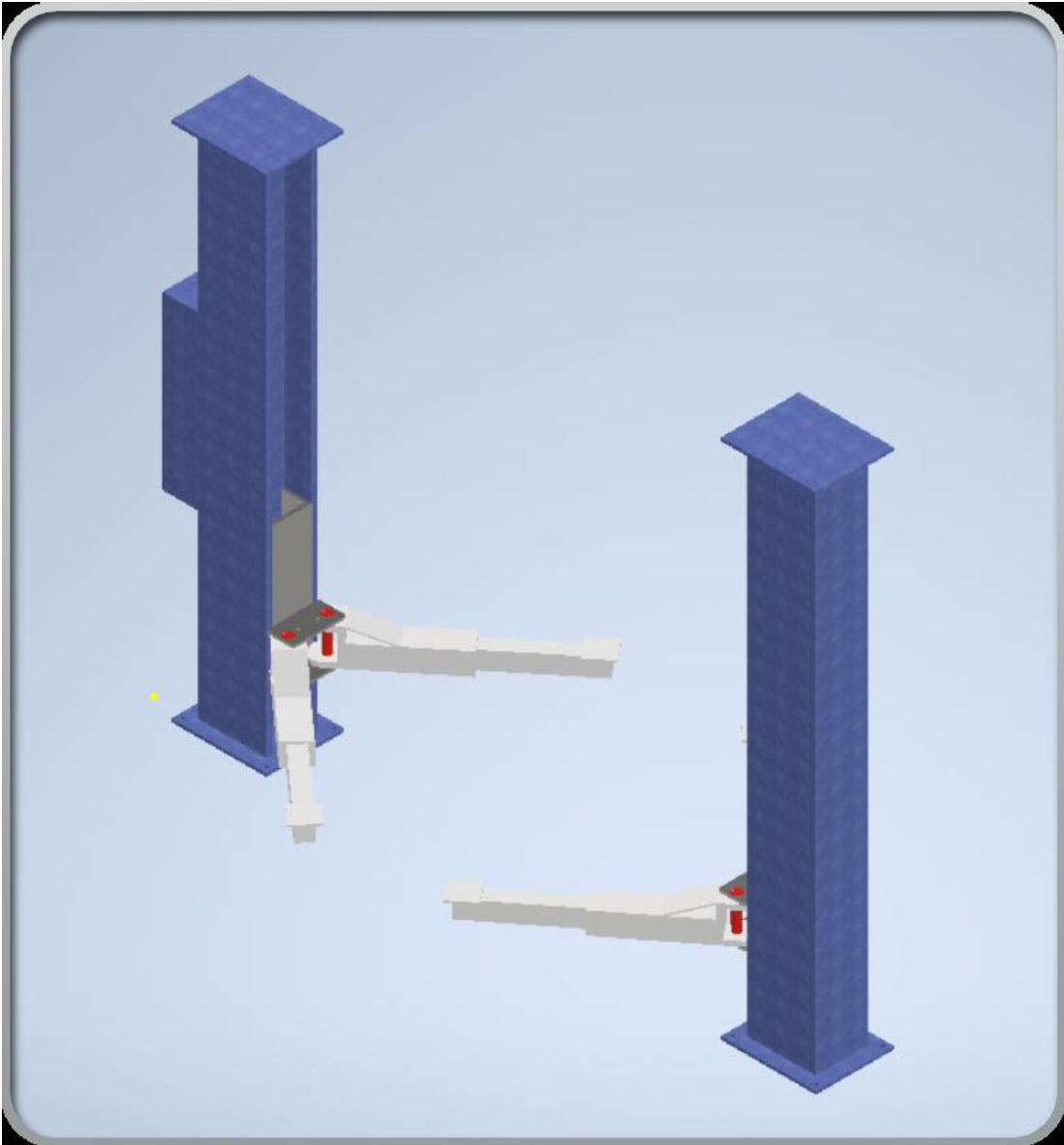
Hydraulic Car Lift (SolidWorks)
Designed a hydraulic car lift for a graded unit — achieved an A. Focused on mechanism design, safety factors, and manufacturability.
Mechanical Engineering portfolio: SolidWorks, Fabrication, and FEA/ANSYS. Engineering you can build: design, test, fabricate.
I’m a builder at heart with a mechanical engineering degree to match. I like projects that start on a notepad, get refined in CAD and analysis, and end up on a bench with swarf on the floor. Highlights include a 6-DOF robotic arm for a mini-Mars rover; materials selection, modelling and validation, and a graded unit where I designed a hydraulic car lift from brief to costed, testable concept. Day-to-day I use SolidWorks and analysis to de-risk designs, then switch to the workshop for machining, welding and assembly. Away from the desk I recharge by going to the gym, hiking, fixing and modifying cars, woodworking, and building PCs. I enjoy meeting new people, asking good questions and collaborating to get from rough concept to something that works first time in the real world. If that sounds like your kind of project, let’s talk.
Designed a hydraulic car lift for a graded unit — achieved an A. Focused on mechanism design, safety factors, and manufacturability.
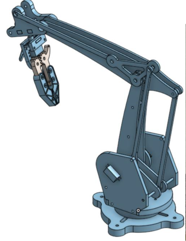
Lightweight, 3D‑printed robotic arm with closed‑loop control using Arduino and an ultrasonic sensor for object detection.
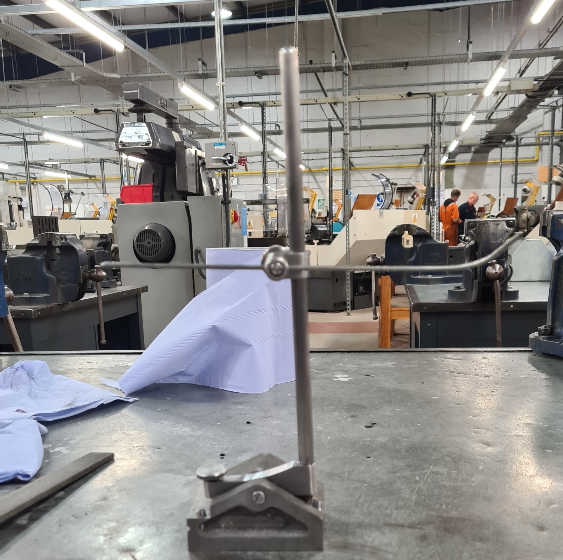
Fabricated from bright mild steel (milling, tapping, welding). Resolved a poorly cast base by reinforcing during fabrication.
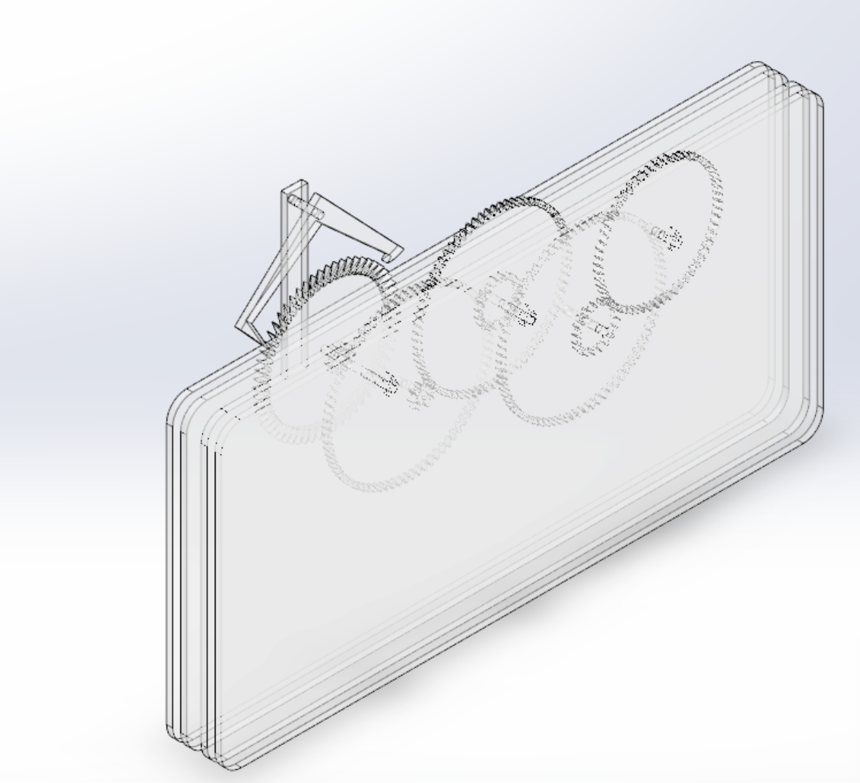
Explored motion studies and linkage timing to achieve accurate time‑keeping; models produced with SolidWorks and AutoCAD.
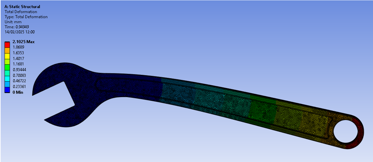
Built and tested a 3D model in ANSYS SpaceClaim, comparing titanium vs. steel for stress/strain and total deformation; included mesh convergence.
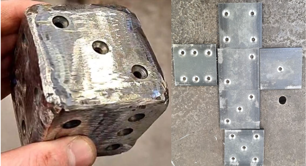
Manufactured an adjustable wrench (mild steel body, brass wheel using a fly press) and a steel die to develop MIG welding skills.
SOLIDWORKS AutoCAD Autodesk Inventor 3D CAD Design for Manufacturing (DFM) Engineering Drawings Bill of Materials GD&T
ANSYS (FEA) Structural Analysis Tolerance Stack-ups Materials Selection Data Analysis
Machining Metal Fabrication MIG Welding Precision Measuring Prototyping Power Tools QHSE
MATLAB Python (basic) C++ (basic) Microsoft Excel Office 365
Teamwork Communication Problem Solving Leadership Presentations Time Management Adaptability
Surveying & Installation Customer Service Operational Efficiency Troubleshooting Industrial Safety